
1.Preparation before commissioning
①、electrical equipment
②、Main PLC:SIEMENS S7-1500 (CPU-1511C-1PN)
③、HMI: SIEMENS TP1200
④、drive:DANFOSS FC300
⑤、electronic wire break detection
- Commissioning software
- Main PLC and HMI:TIA Portal V15.1
- drive:MCT-10
USB cable, used to adjust the parameter of the drive.
2.Wiring checking
①、Before the equipment is powered on, the internal circuits of each component and the connection between components must be checked to confirm that the main circuit and the air switch that controls the power supply are in the off state.
②、Normal line check
a. Whether the shielded wire is used in the place where the shielded wire should be used according to the drawing requirements. Whether the equipment is well grounded, the grounding resistance of the ground wire should be as small as possible (separate grounding should not be greater than 4 ohms).
③、Check the electrical wiring
In order to ensure the safety of power-on, check the circuit carefully, and check whether the peripheral circuit is correct and consistent with the schematic diagram in combination with the electrical schematic diagram and the electrical wiring table.
④、Make sure there is no cross-connection between strong and weak currents.
Whether the three-phase resistance of all motors is balanced, whether the 24V power supply and 220V output are short-circuited, and whether the connection is short-circuited, broken, and grounded.
⑤、Check the copper bars and brake connections in the electrical cabinet
Pay attention to check the connection of copper bars in the electrical cabinet. The DC busbars DC+ and DC- must not be reversed, short-circuited or grounded.
⑥、Check the brake resistor
a. Measure the resistance value of the braking resistor and check it with the resistance value marked on the drawing.
b. The braking resistor must not be short-circuited to ground.
7. Check the wiring of the motor encoder
Check the encoder wiring according to the drawing.
EB50B8-L4HR-1000 encoder wiring color comparison。
3.Whole line powered
1. Firstly, power on the control loop power supply, measure whether the DC 24V voltage is normal, and check whether there is any abnormality after the power transmission in the PLC power supply
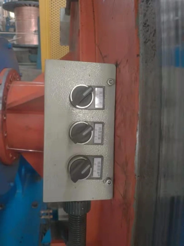
2. Check whether the proximity switch on the device is working normally, adjust its sensing distance, such as meter counting, positioning in place and so on. 3. Test the tension of the spool on the cage, spool locking, and whether the switch for clamping/releasing the spool is normal, as shown in the figure: 0 is closed, 1 is open. The tension control of the spool is to tighten the spool, and the spool is locked with electricity, and they are switched on and off. The locking of the spool is to control the opening or closing of the locking plate. The spool tightness controls the
clamping or loosening state of the spool clamping cylinder.
4. The first step of the action sequence is to select the tension, the second step is to lock the spool, and the third step is to tighten the spool.
5. The button statin of the cage is as below:
a. Operating button box components, including the up and down of the loading device, the forward and reverse jog of the cage, the forward and reverse operation of positioning, the alarm bell of the equipment, the jog of the whole machine, the quick stop, and the emergency stop.
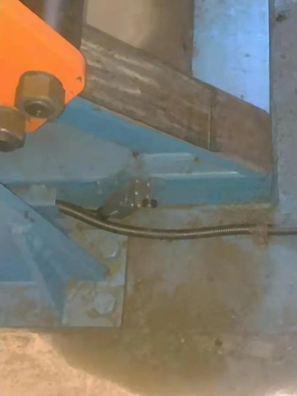
b. Upper limit switch of the loading device.
- The down limit switch of loading device
b.Position of the approach switch for automatic stop.
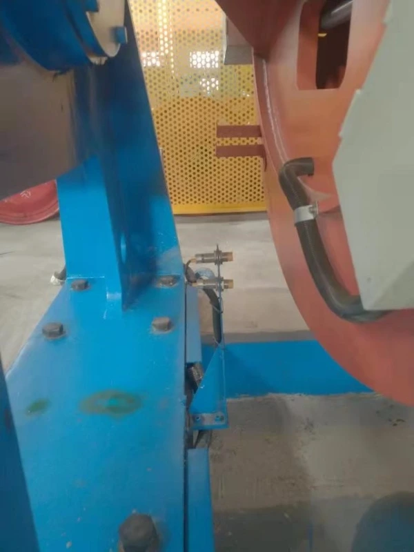
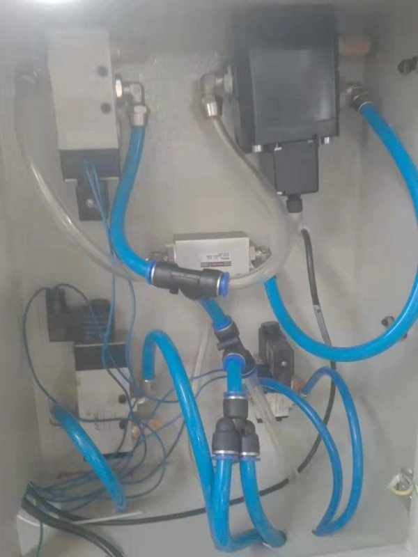
6. The red marked parts are the cage brake solenoid valve and the brake proportional valve, the other large proportional valve is the cage inlet solenoid valve, and the small one is for the rotary air inlet, the cooling solenoid valve of the air bag.
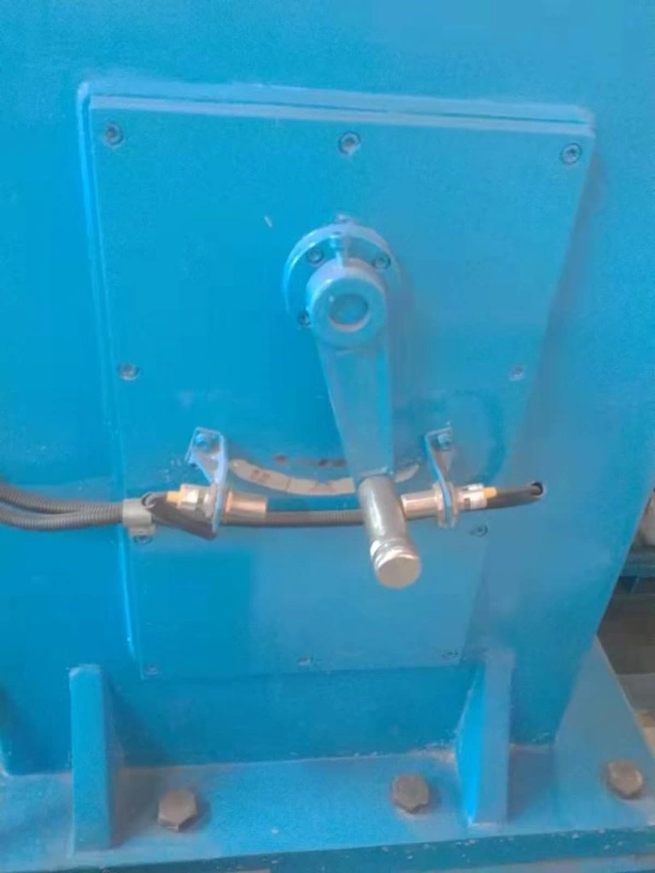
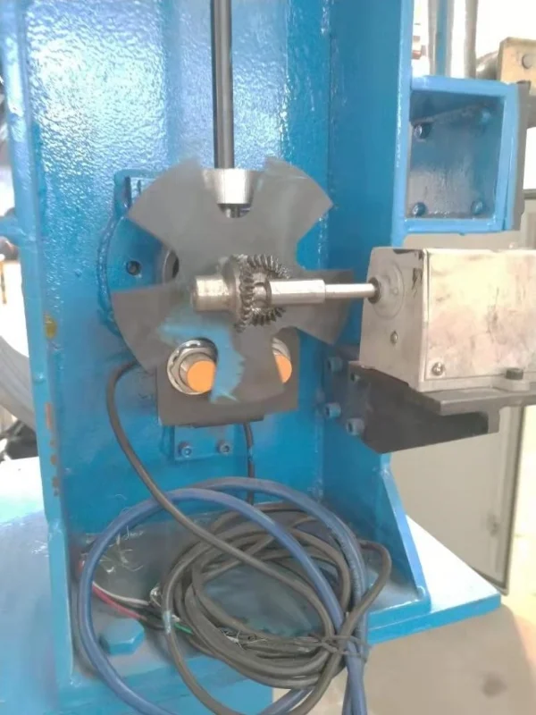
7. There are three positions in the picture, the middle is neutral, the right is fast, the equipment is running normally, and the left is slow positioning, which is required for the loading the bobbins. Proximity switch detection is in place.
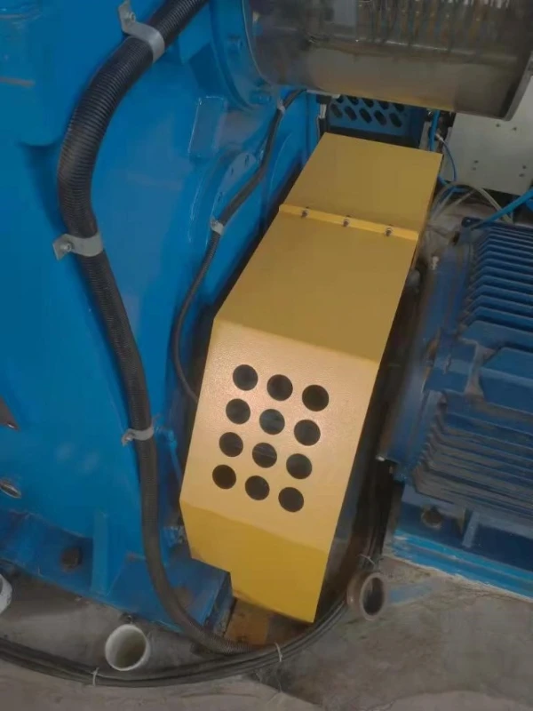
8. Below the yellow protective cover is the oil pump motor.
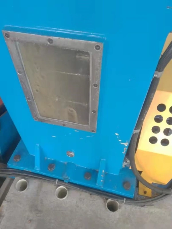
9. When the machine is running, look at this visual window to confirm whether the oil pump is working correctly.
10. Electric wire break adjustment.
11. In the production process, if there is a reel, press the red button in the picture, the green light will turn on to make it in the working mode, and when the green light turns red, it means that a wire break problem is detected. If there is no reel, then close picture 1 and 2.
12. Parameter setting
The related parameters are already set before the machine shipment.
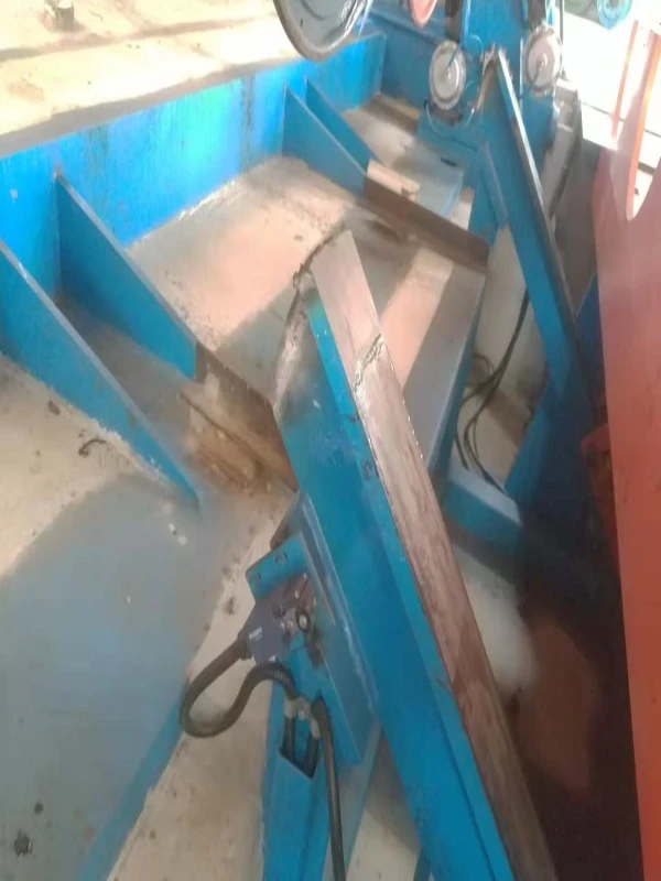
13. Adjust the loading position
Use the full loaded reel to debug the slow speed automatic positioning device, adjust the position of the induction blocks in each equal part of each cage, and weld the limited switches for the going up and down of the loading unit.
14. Trial running for the whole It is available to do the trial running of the whole line after the above checking finished.